
Alternator relocation and IM547 conversion
The hot side of the NC engine bay is cramped from the factory with the alternator and exhaust manifold in close proximity with manifold heat shielding and cooling ducts to make it work. This makes it challenging packaging a low mount turbo setup and some trade offs have to be made.
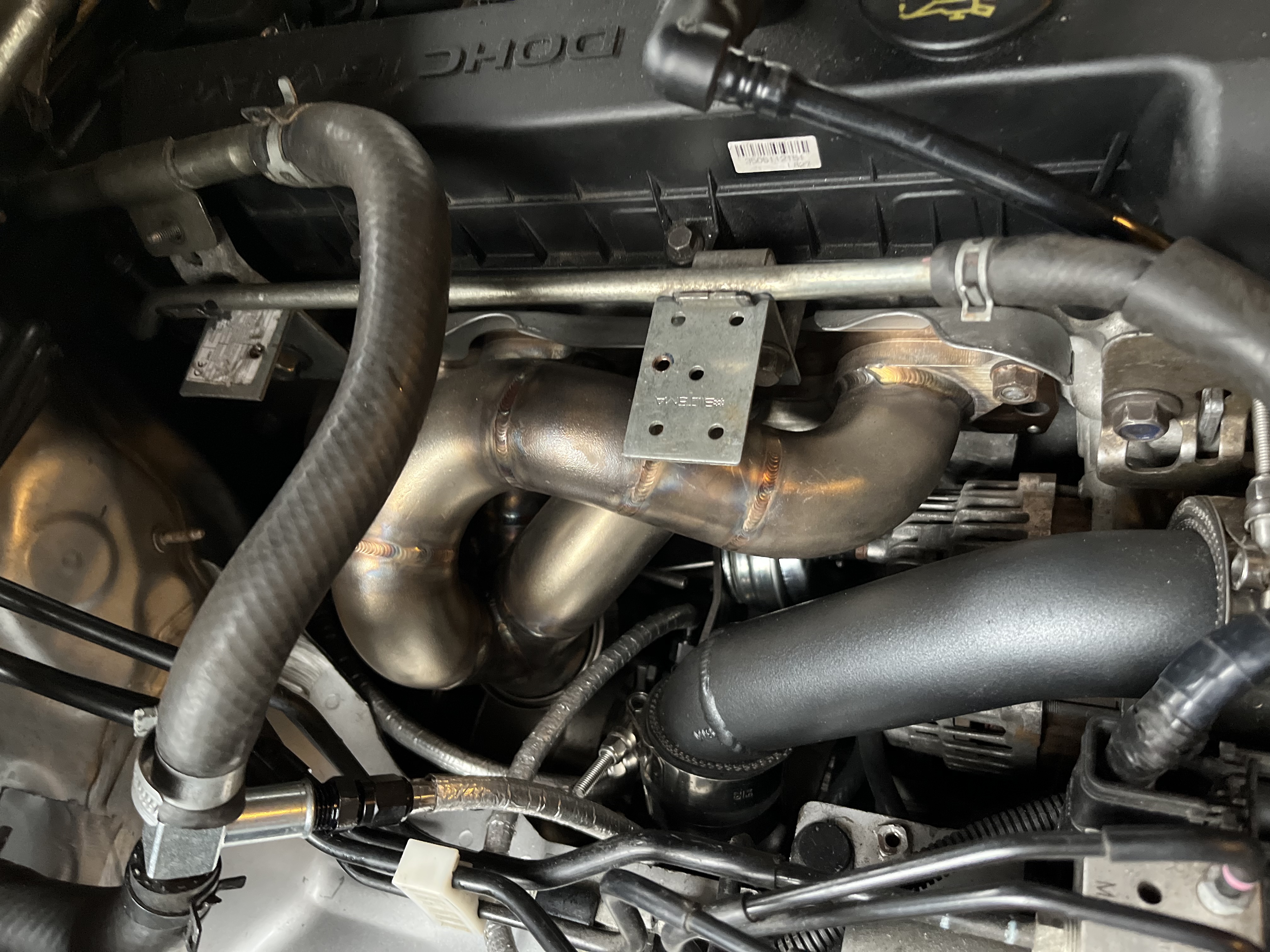
No room for the OEM alternator cooling duct. The business end of the alternator with electronics is exposed to intense heat from the manifold. This is doomed to fail.
Luckily Lawrence over at tracktuned.co.uk figured out how to relocate the alternator back i 2019 and documented it in great detail including the Mazda3/6 alternator, belt and pulley part numbers:
Mazda 3 alternator part number: A3TJ1091 110A
Mazda 6 alternator part number: A3TG1391A 90A
Belt GATES 6PK1470
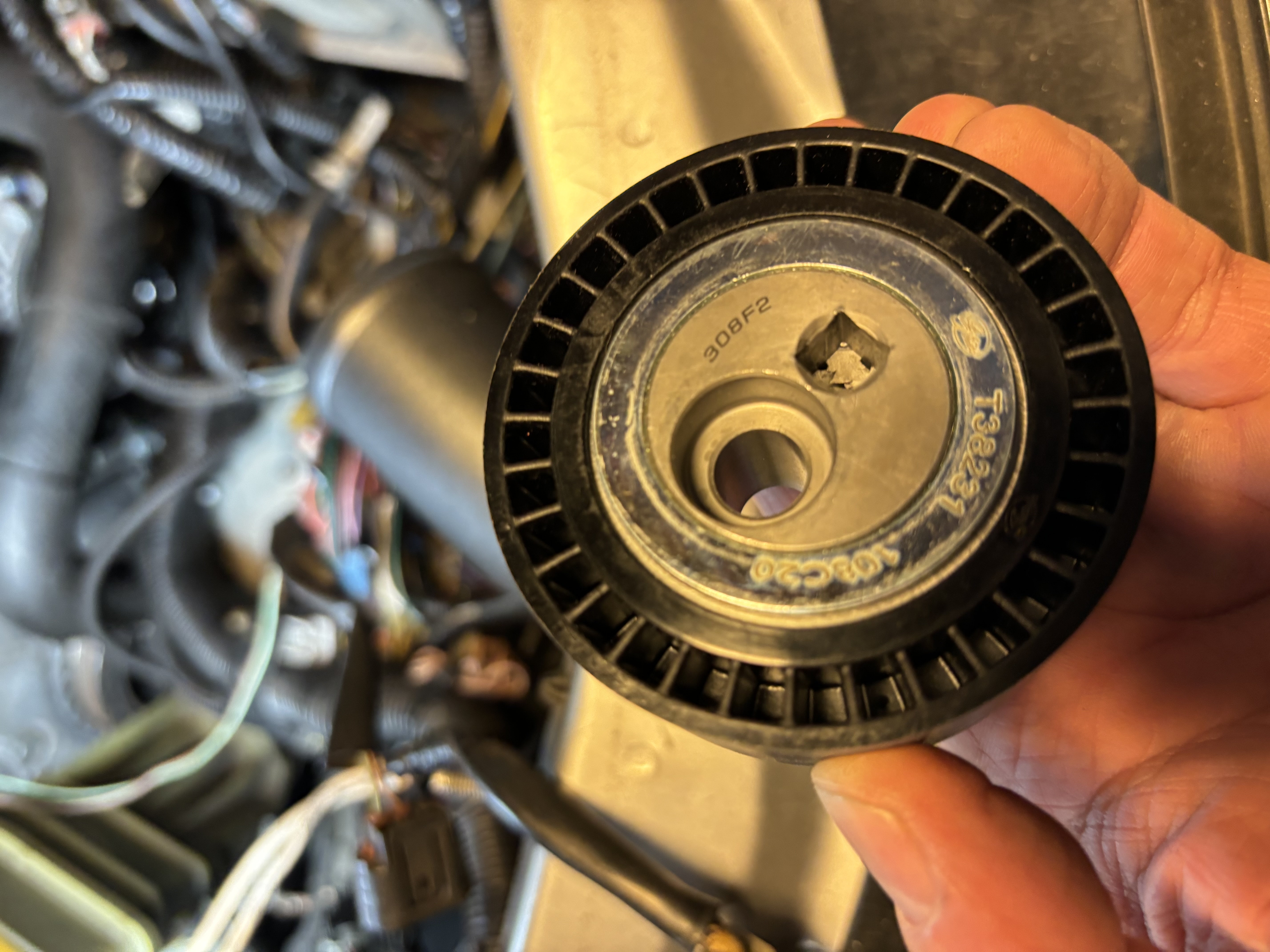
Pulley GATES T38231
He is also selling kits for this which at the time of writing was way cheaper than what I paid for sourcing each individual part locally.
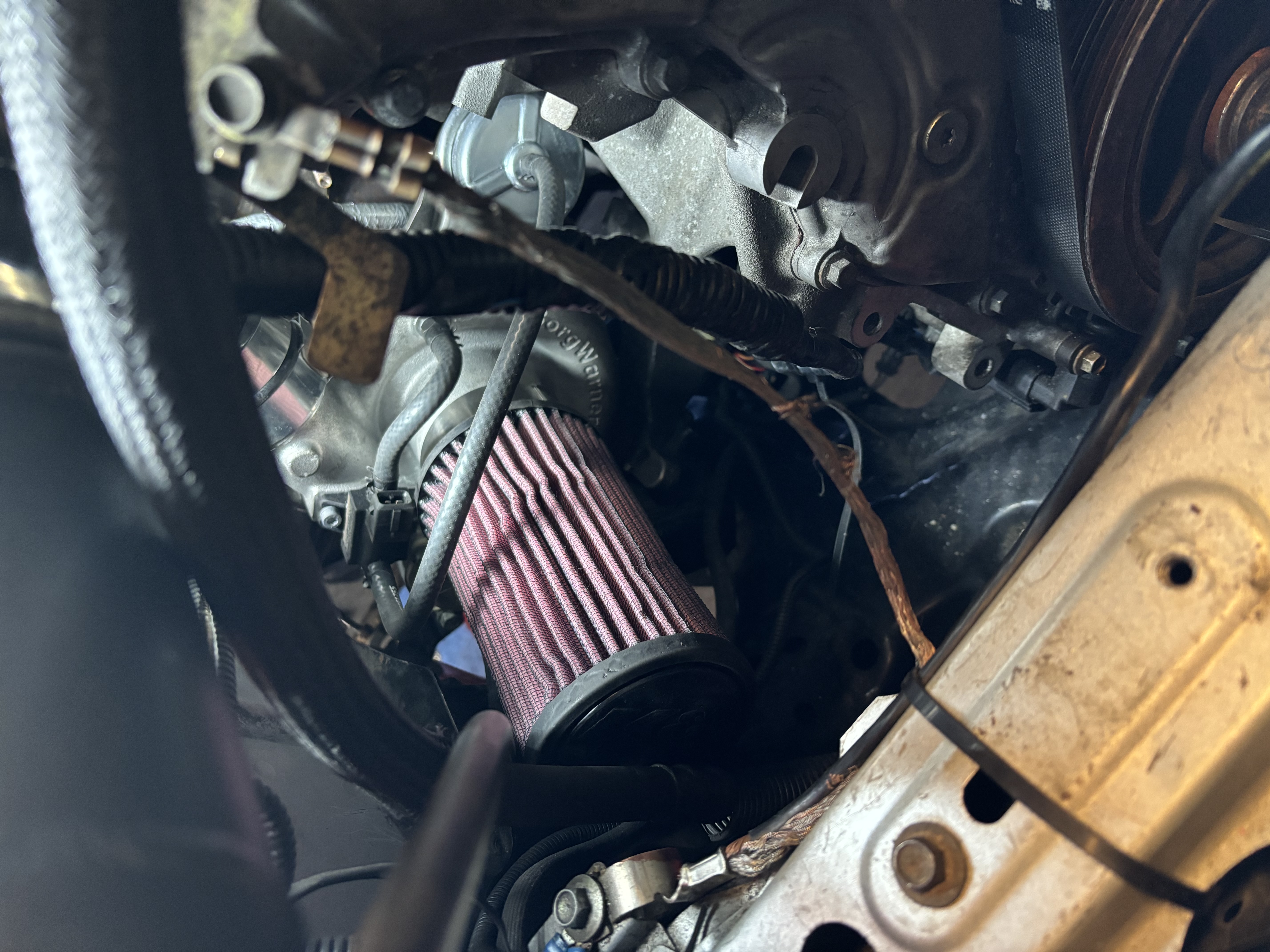
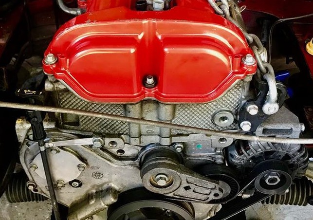
Alternator and tensioner removed. Lots of room for airflow and access to turbo.
 |
 |
I have no good pics of the routing but have a look at the link above.
TLDR :
- Alternator is replaced by Mazda3/6 part that fits in the AC location. The stock one can not be reused.
- OEM tensioner and hot side idle pulley is eliminated by replacing the cold side idler pulley with an eccentric tensioner pulley.
This was a nobrainer for me as my car do not have AC.
Pulley works by having the bolt off center. By rotating it using the square socket hole before securing the bolt one can set a static tension on the belt.
Cons: It does not compensate for belt stretch over time. I had to re-tension once, but the real test will be next track day.
Update 2024.09.06: After four months including 3 x trackdays the tensioner had to be maxed out but stretch seems to have settled.
Backup plan is to add an Ecotec tensioner if the belt does not settle:
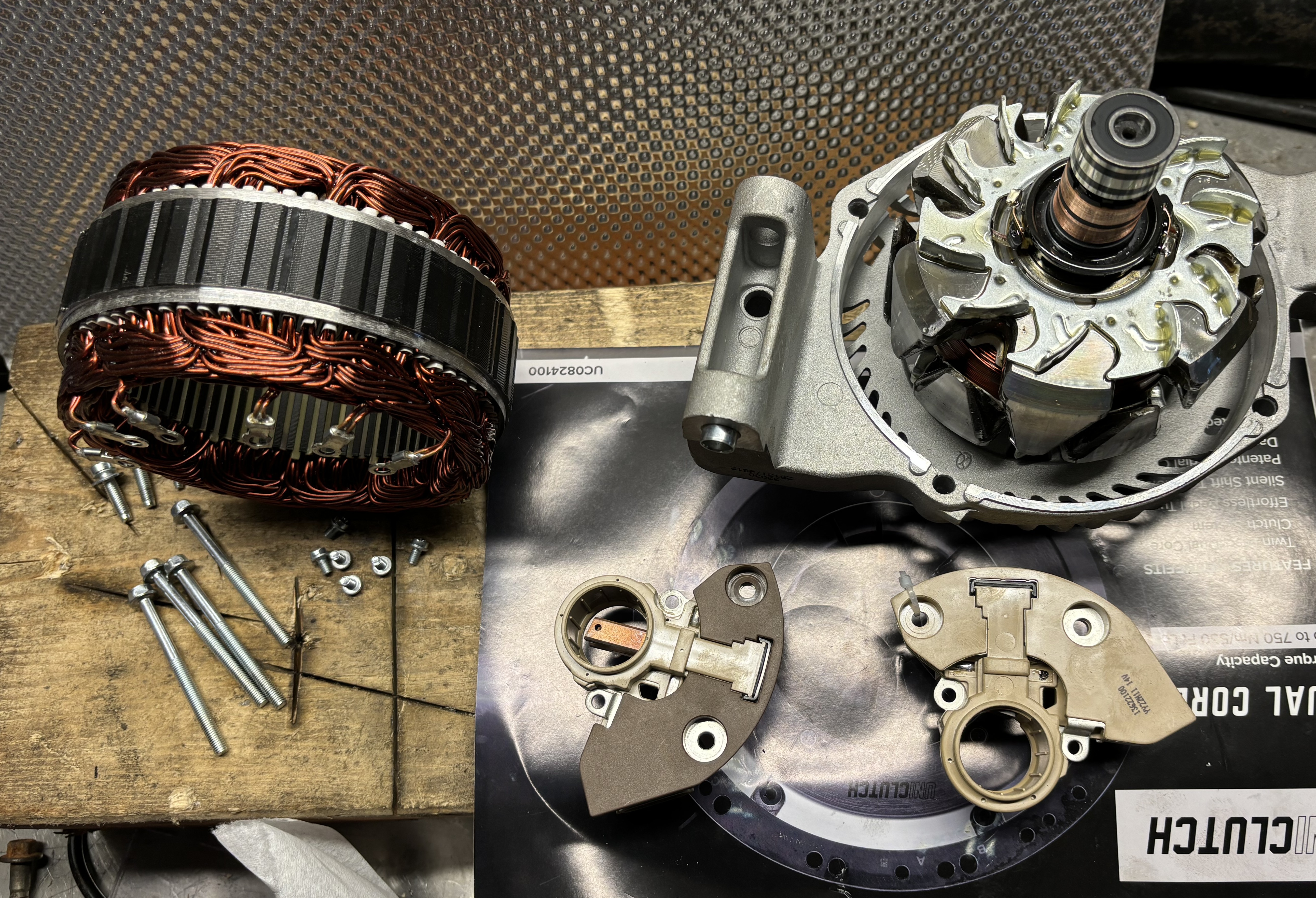
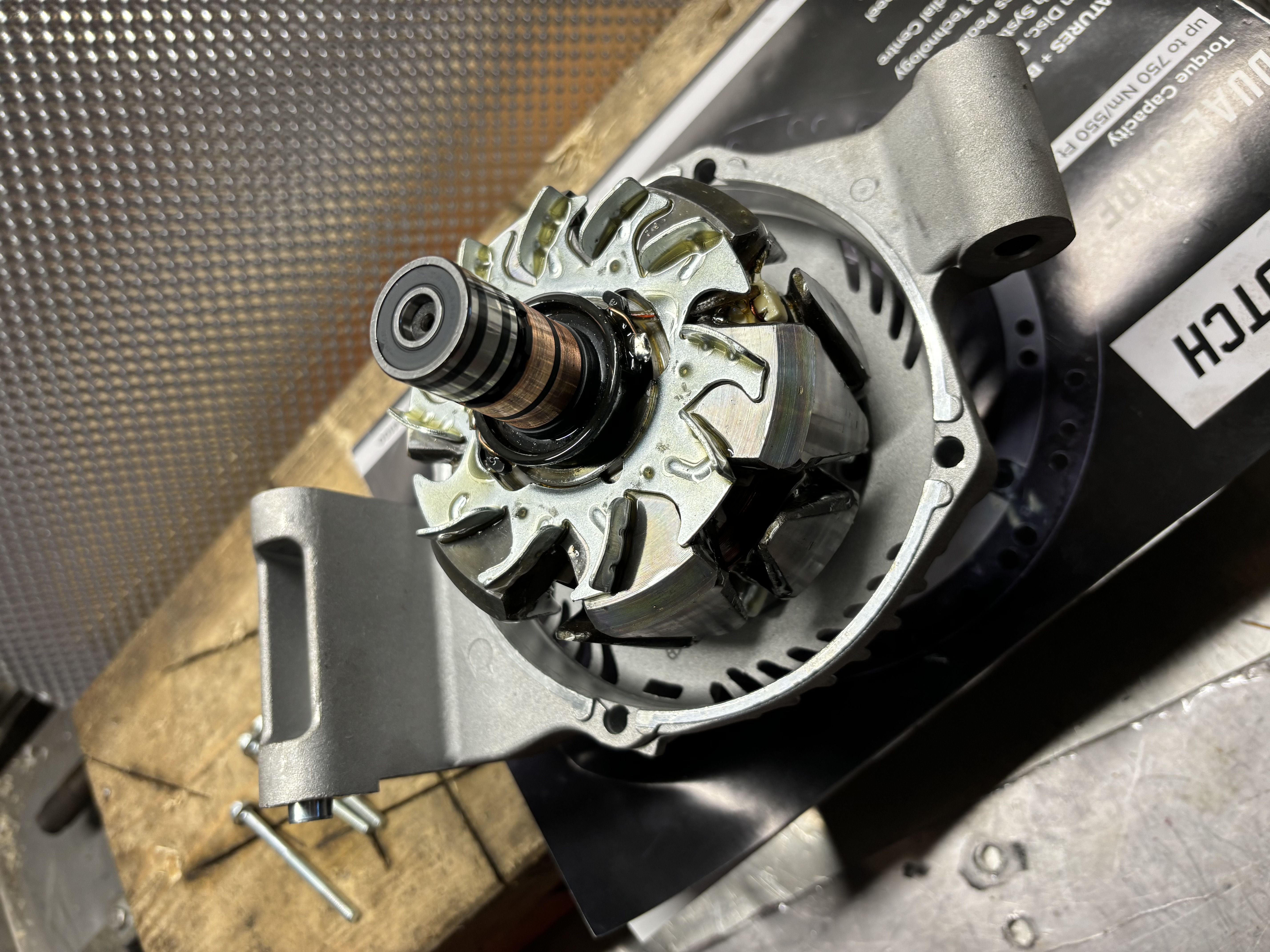
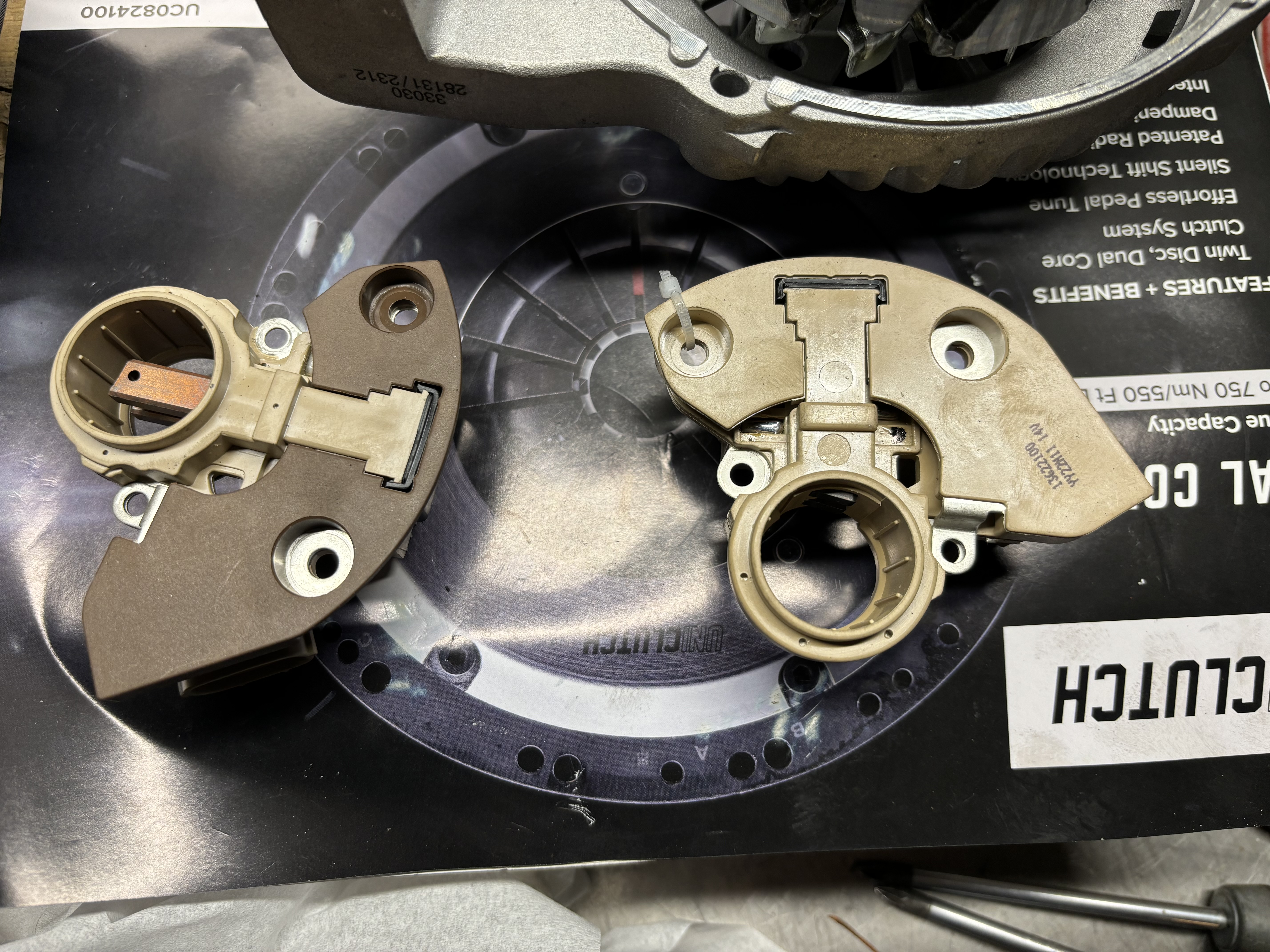
While messing with the alternator I also decided to replace the voltage regulator with a non OEM controlled IM547 controller. My EMS is not able to control the voltage by PWM for whatever PID combo I used so had to mock up an Arduino which fakes a trigger signal to the OEM ECU for voltage control… While working great it’s too much complexity and failure points.
The conversion is partly documented here on m.net as well as tracktuned.co.uk
I first tried it on an old Mazda3 alternator I bought years ago. All bolts snapped, so I bought the cheapest non OEM A3TJ1091 110A I could find and it worked fine. Any IM547 regulator should work.
 |
 |
 |
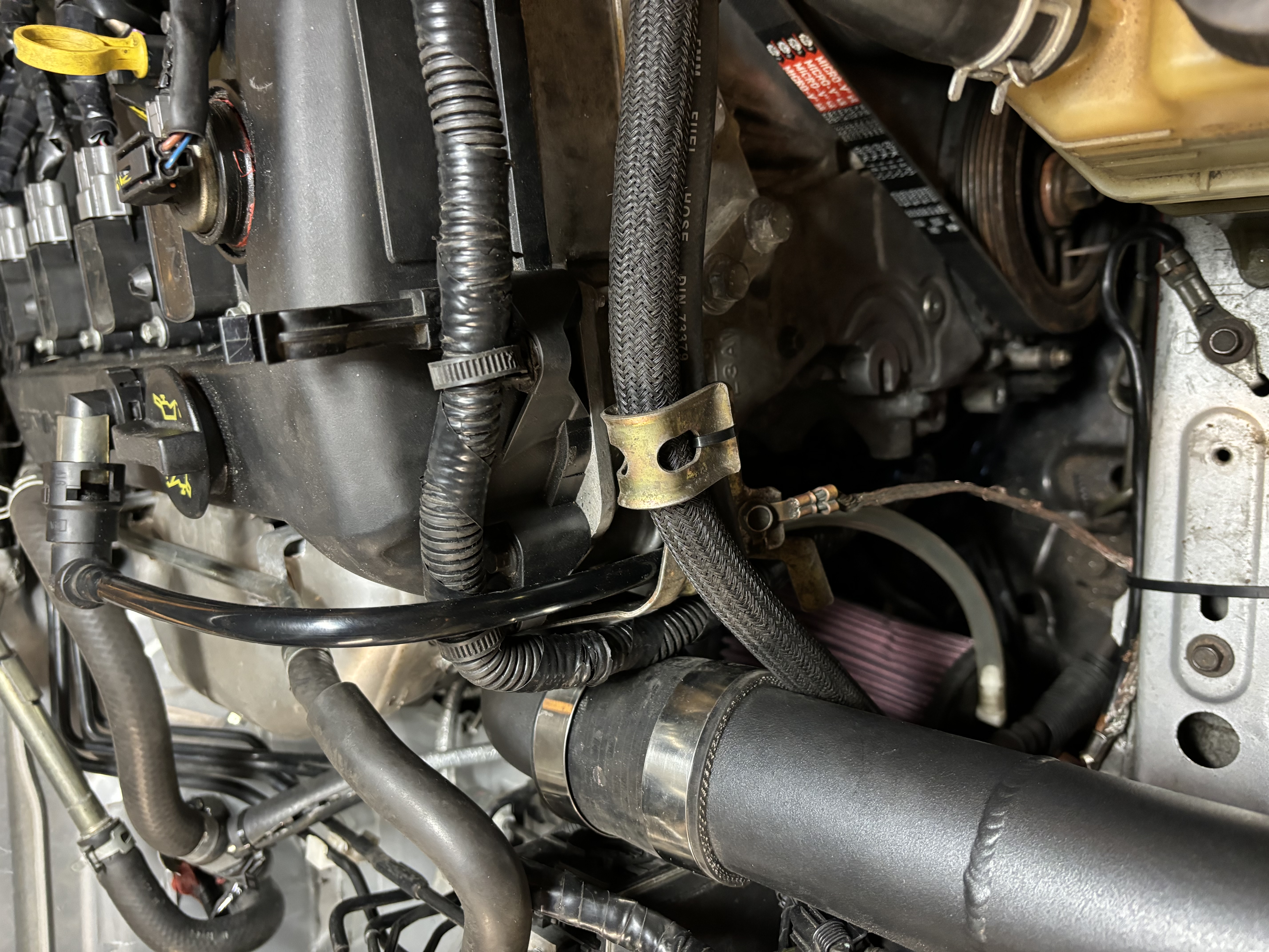
It’s a tight fit. I had to push the steel coolant pipe closer to the frame rail to make it clear the terminal. See modification for mount for clearing the steering shaft.
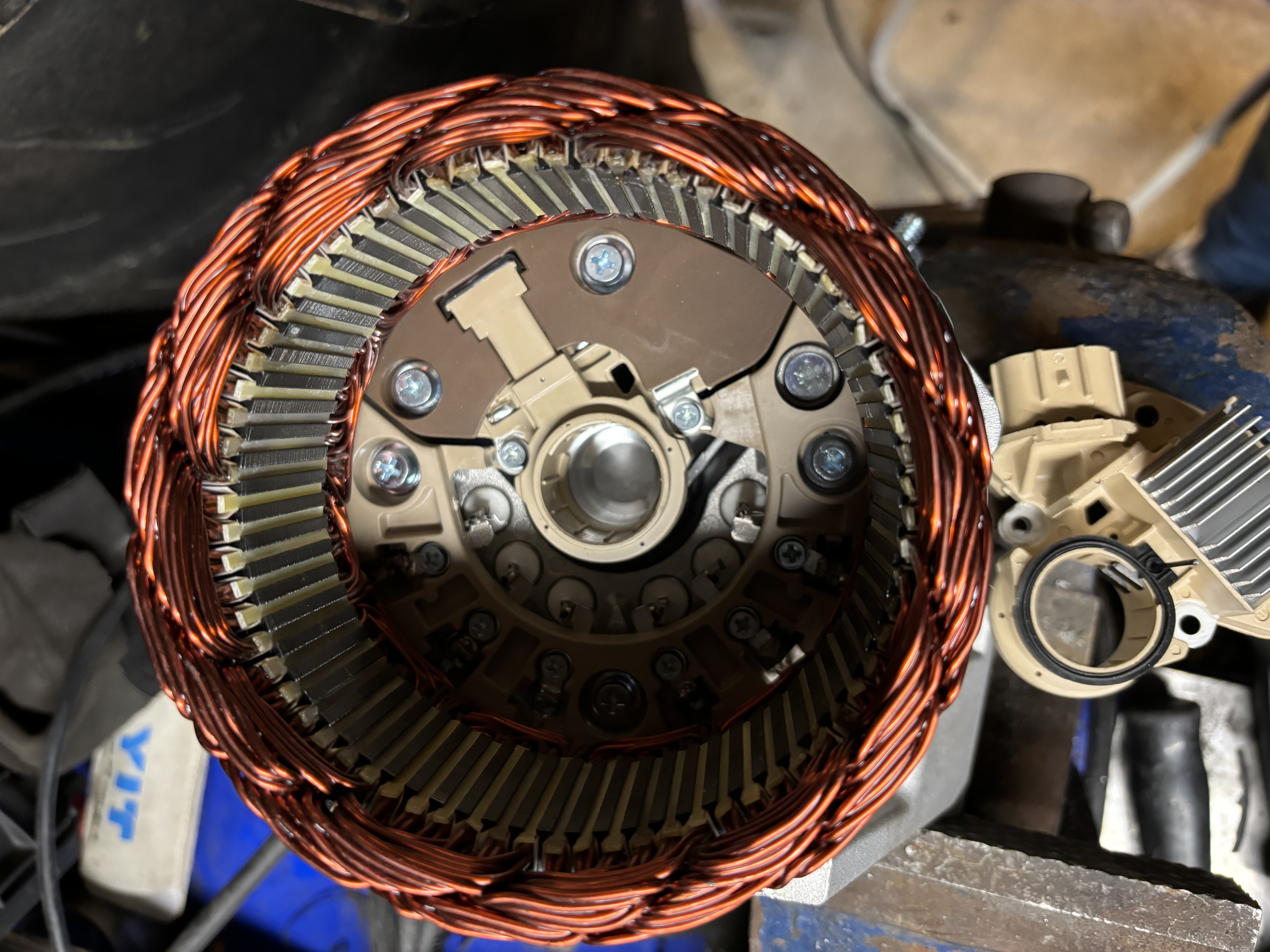
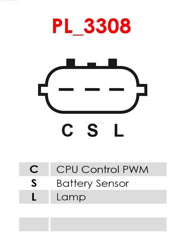
The wiring is simple but awkward. This is like 1920’s tech where the controller senses the voltage via a lamp bulb or something.
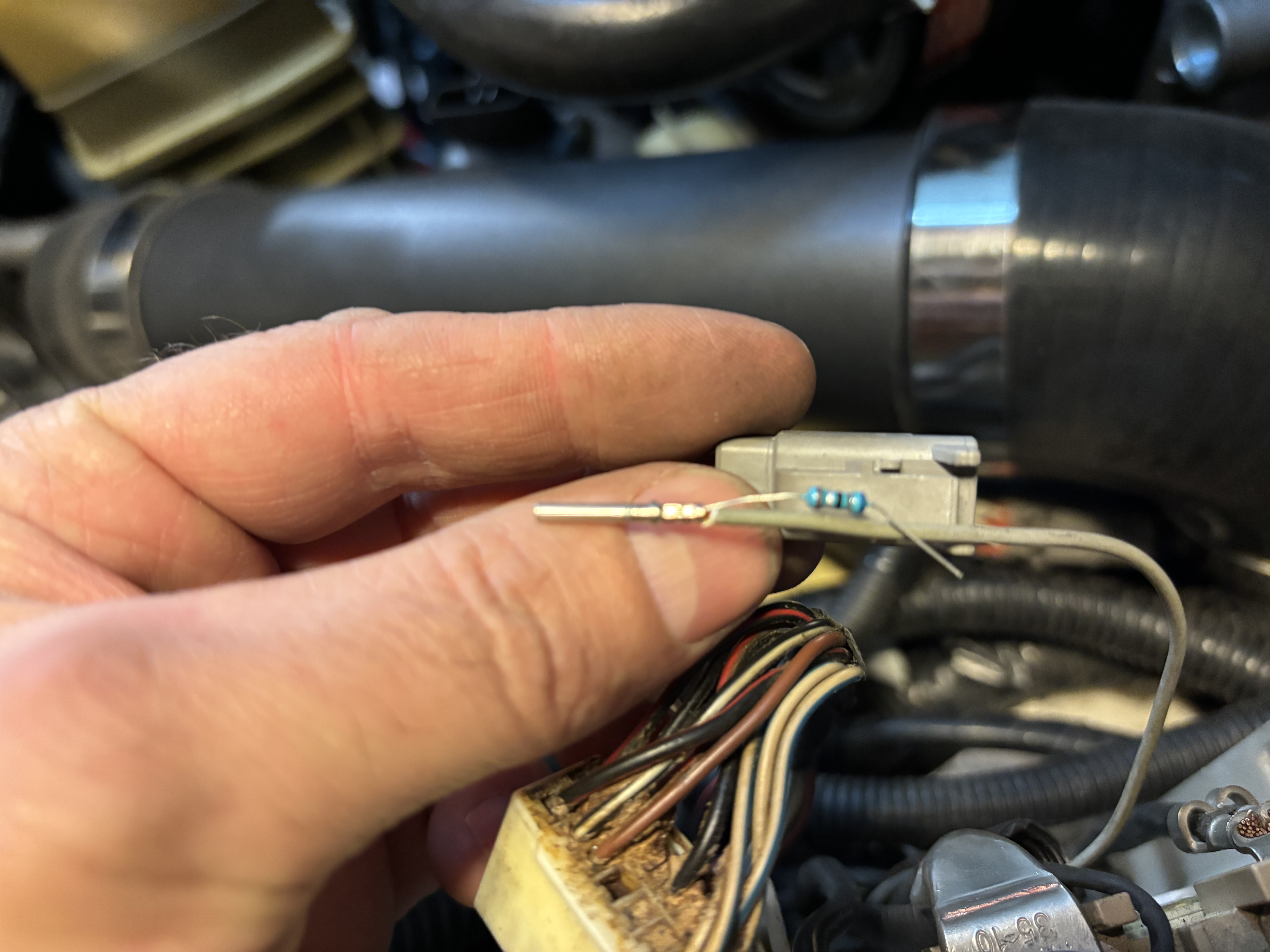
Only use L and S terminal
 |
 |
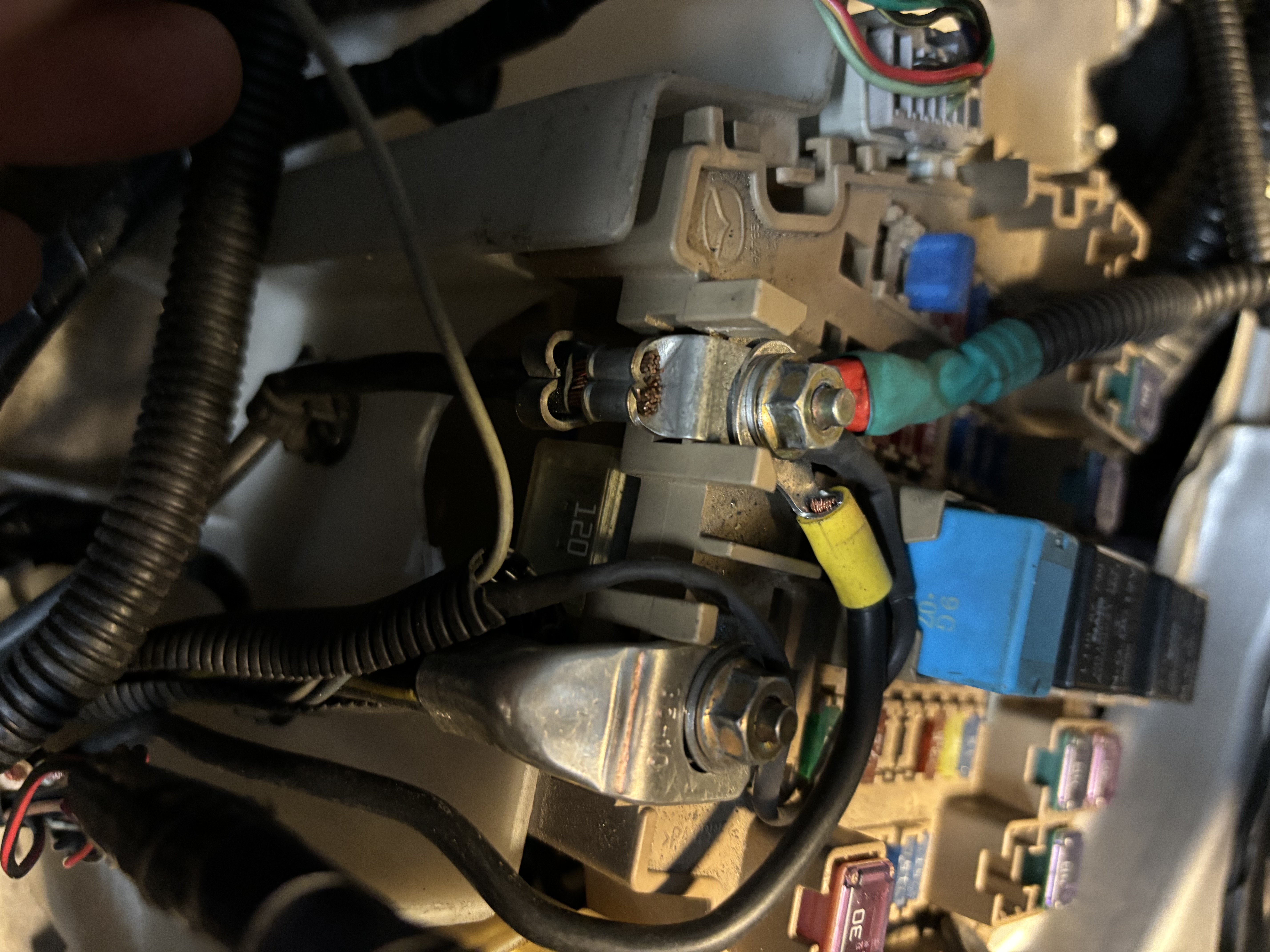
( Ignore the red and yellow wires on the left terminal in the pic as they are for EMS B+ and Battery relocation)
- Reuse the OEM double white B terminal wires from alternator which goes to the right terminal in the fuse box as per pic. Mine is black as I used one from a Mazda3 which was correct length.
- The S (Sense) wire goes to the left terminal which is directly from the Battery+
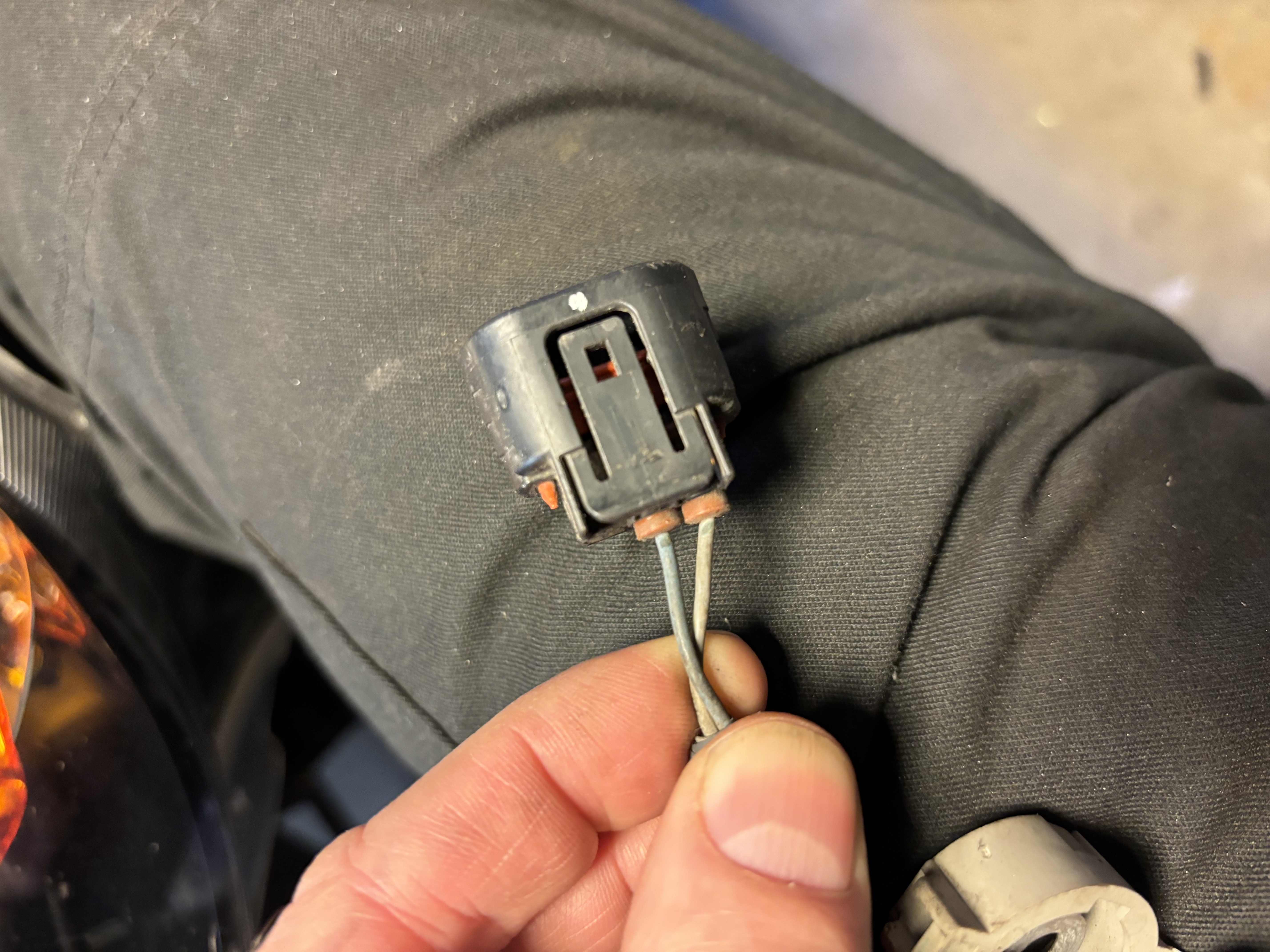
- The L (Lamp) wire goes to switched positive wire (key on) but need either a 12v bulb or a 150 ohm resistor in line. Supposedly this is needed for the regulator to detect current flow when there is a substantial difference between the system or batt voltage and the alternator charge voltage something something. I tapped into the red and black wire from the plug in the right picture but there might be a more accessible switched positive source in the fuse box.
 |
 |
Charging works great. I have never seen below 13.8 or higher than 14.0 volts. Very happy to no longer be dependent on the OEM ECU for this task.
Comments