Flyinmiata Supercharger installation
I had the pleasure of installing the FM Supercharger for the NC MX-5 back in May and I thought I’d share share some pics and experiences from the installation.
For a lot of info and pics of the SC components and packaging check out my previous post here:
A closer look at the “Cosworth” MP62 supercharger kit for Mazda MX-5 NC
The installation was a lot of work but pretty straight forward thanks to FM’s excellent installation manual. It is quite a big job involving a lot of disassembly, splicing of wires and many components. I also did several alterations to the original setup that took longer than I expected ,like the Mustang Cobra actuator, ID1000 injectors, 2.5bar TMAP, W2AIC reroute, alterations to the wiring. All which added to the installation time. I was also not aware that the kit will not work without the A/C compressor pulley so I had to order a used compressor just for this purpose…
I think BBR version of the same kit has a dammy A/C pulley which they might sell separately.
This will not be a installation guide. Just a bunch of pics and some comments.
The first thing on the list was to disassemble the stock IM and fuel rail. The EU version has the VariableTumbleControlSystem butterfly in the manifold flange for better… something..
The SC is a nice but expensive way to get rid of those. The red discoloration on the butterflies is from the E85. I have no idea why. I had to change tophats on my trusty ID1000 injectors to make them fit the NC fuel rail. Stock fuel rail in the picture, the SC comes with its own rail for packaging reasons I guess.
<div class="separator" style="clear: both; text-align: center;">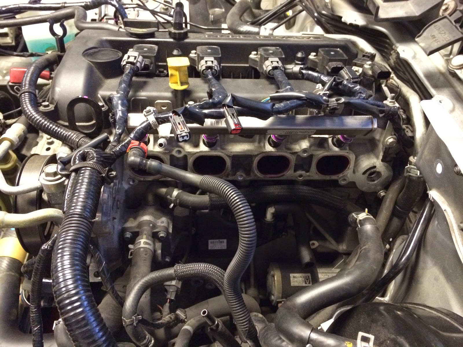 </div>
<div class="separator" style="clear: both; text-align: center;">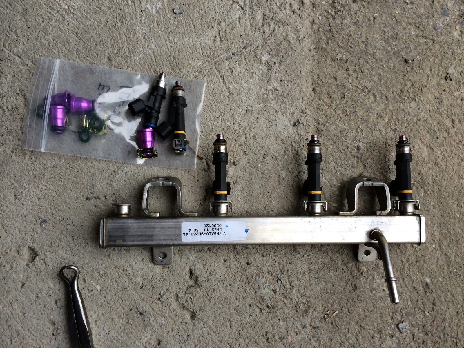 </div>
<div class="separator" style="clear: both; text-align: center;">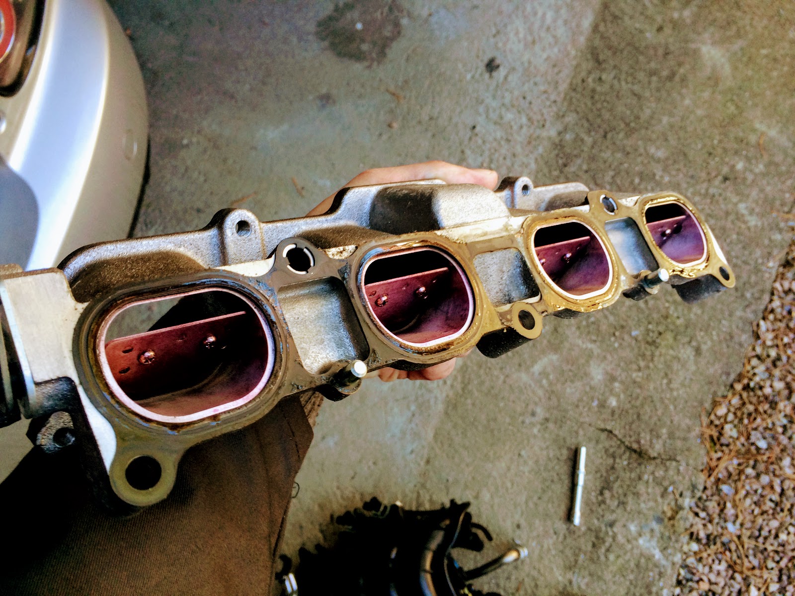 </div>
Stock IM has o-rings on the flanges. It also uses some kind of VICS system for added resonance chamber volume. Both the VICS and VTCS is deleted with the SC. The stock 1.5 bar MAP (this is not a TMAP) is supposed to be reused but does not work well with my 2.8” pulley :)
<div class="separator" style="clear: both; text-align: center;">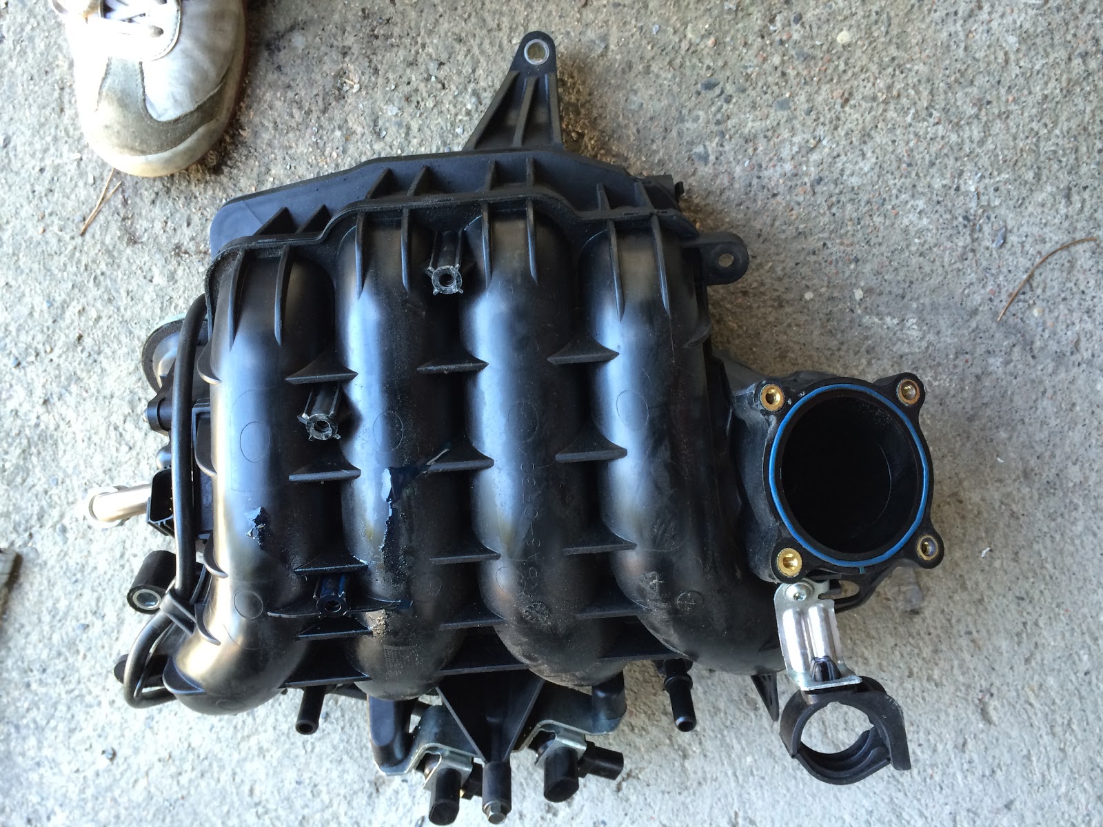 </div>
<div class="separator" style="clear: both; text-align: center;">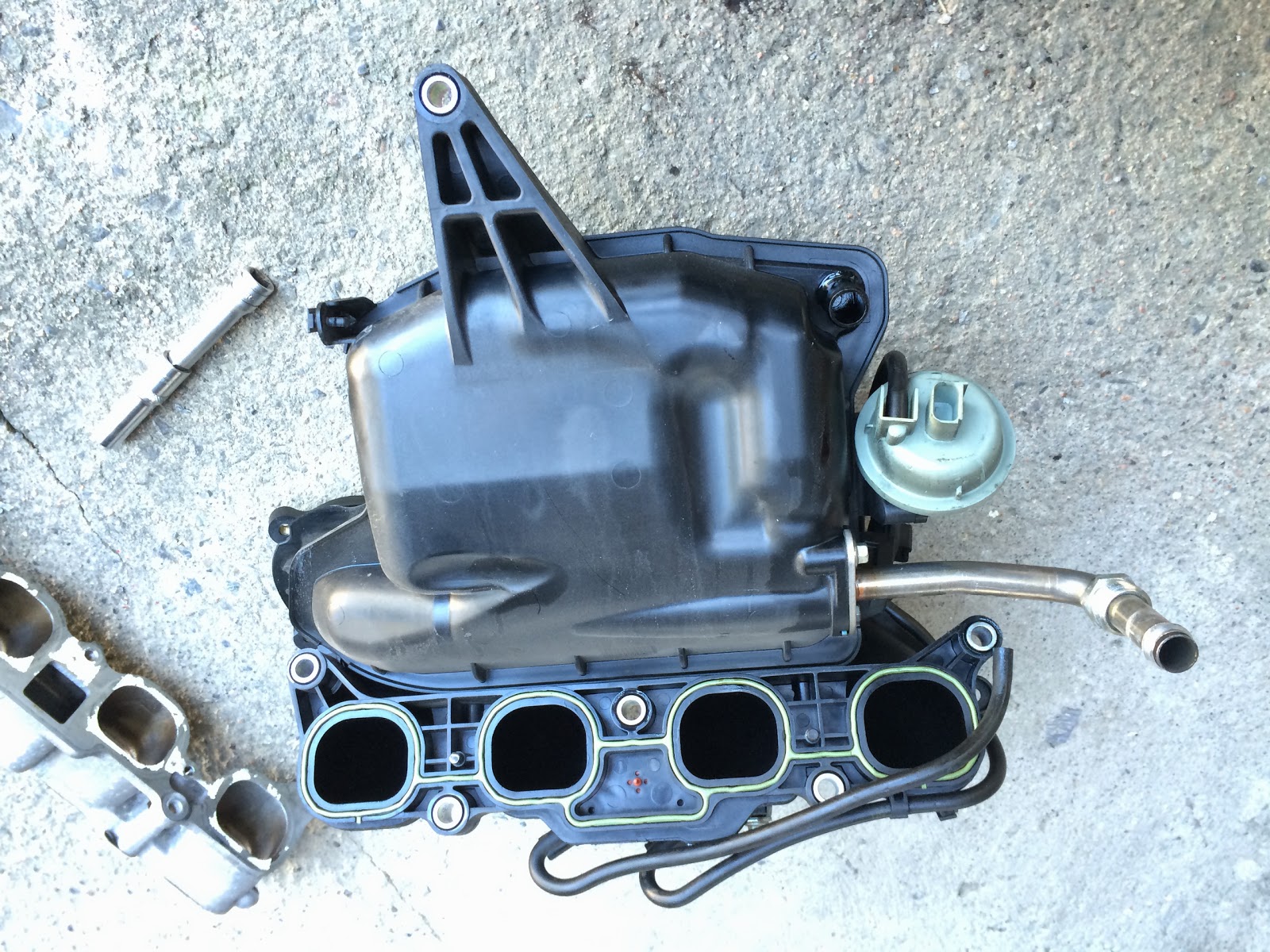 </div>
<div class="separator" style="clear: both; text-align: center;">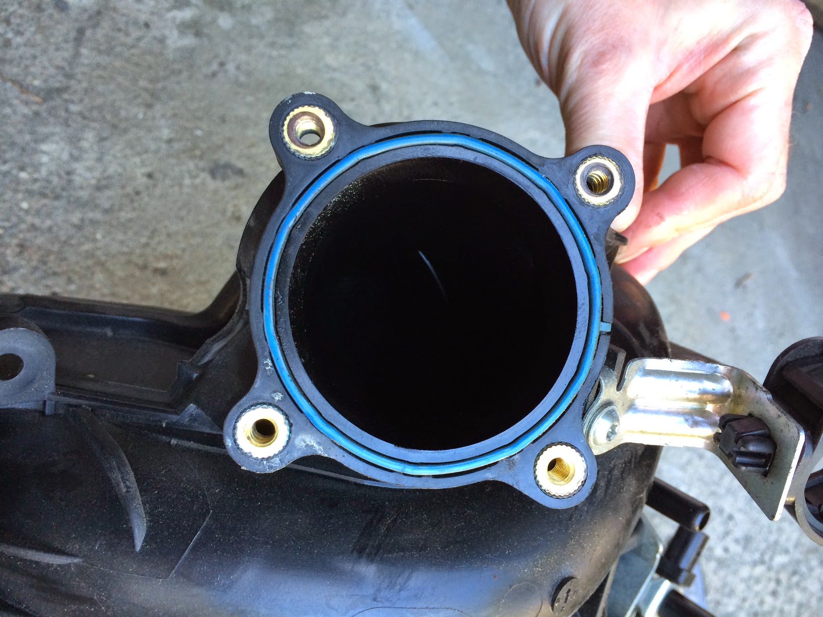 </div>
<div class="separator" style="clear: both; text-align: center;">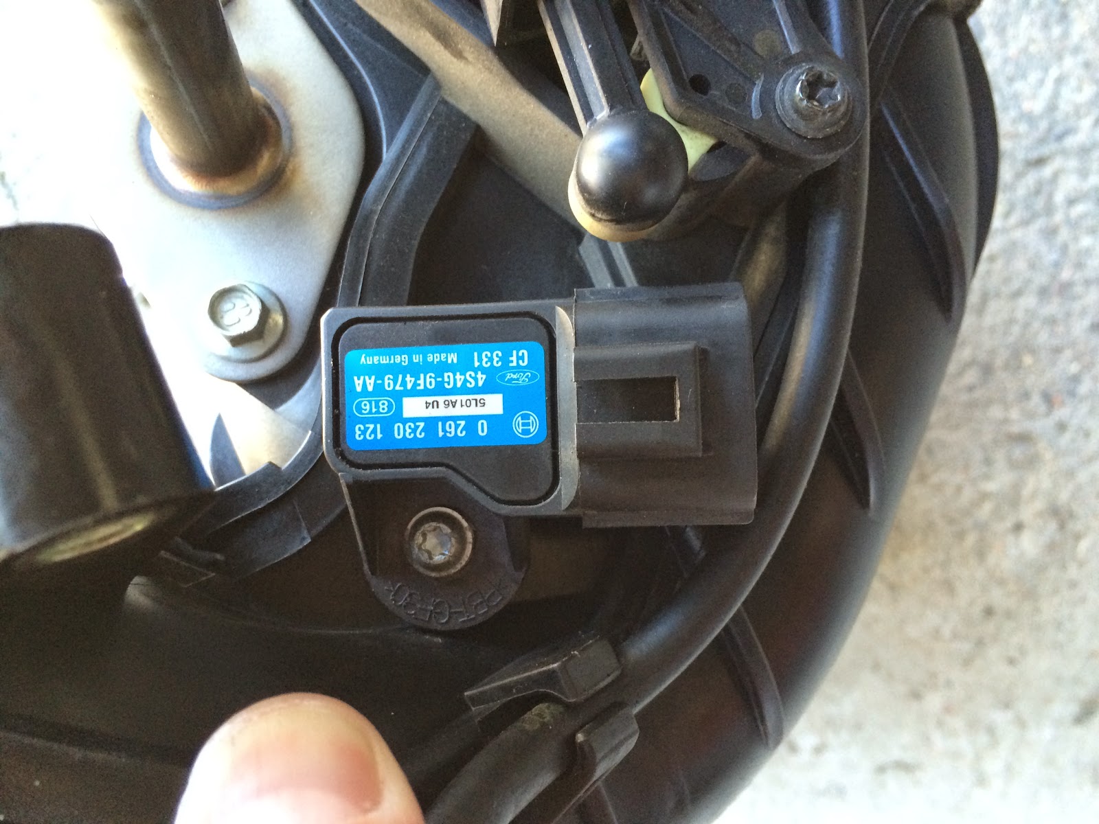 </div>
Before lifting the SC in place it is really important to bend the fuel line (metal part) as not to kink the plastic tube during installation. Also bend the break lines so they are flush to the firewall so the actuator arm can move freely. It is really important to read the instructions and secure the breather and water hose properly as you don’t want to have problems with stuff under the SC later as it is impossible to reach. Also be sure to test the thermostat as there have been several reports of bad Stant thermostats that are included in this kit. Read about it here: http://forum.miata.net/vb/showthread.php?t=405900
<div class="separator" style="clear: both; text-align: center;">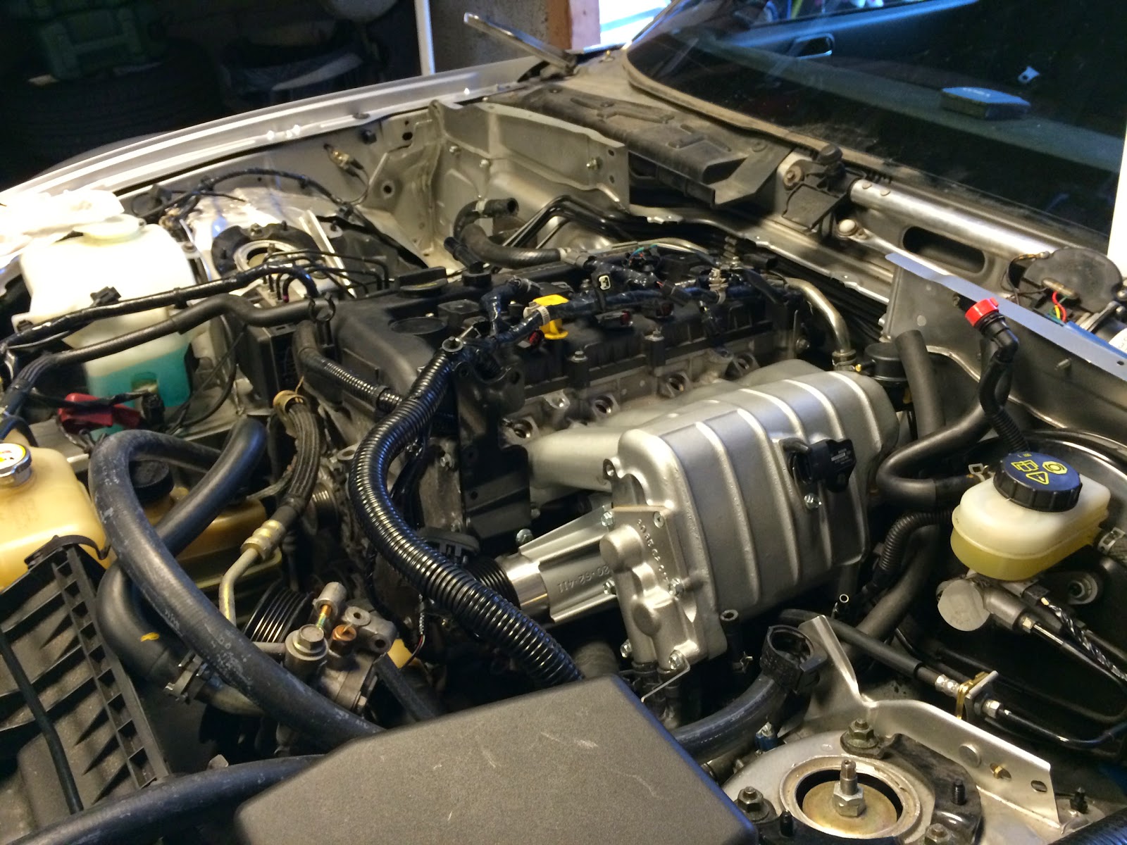 </div>
<div class="separator" style="clear: both; text-align: center;">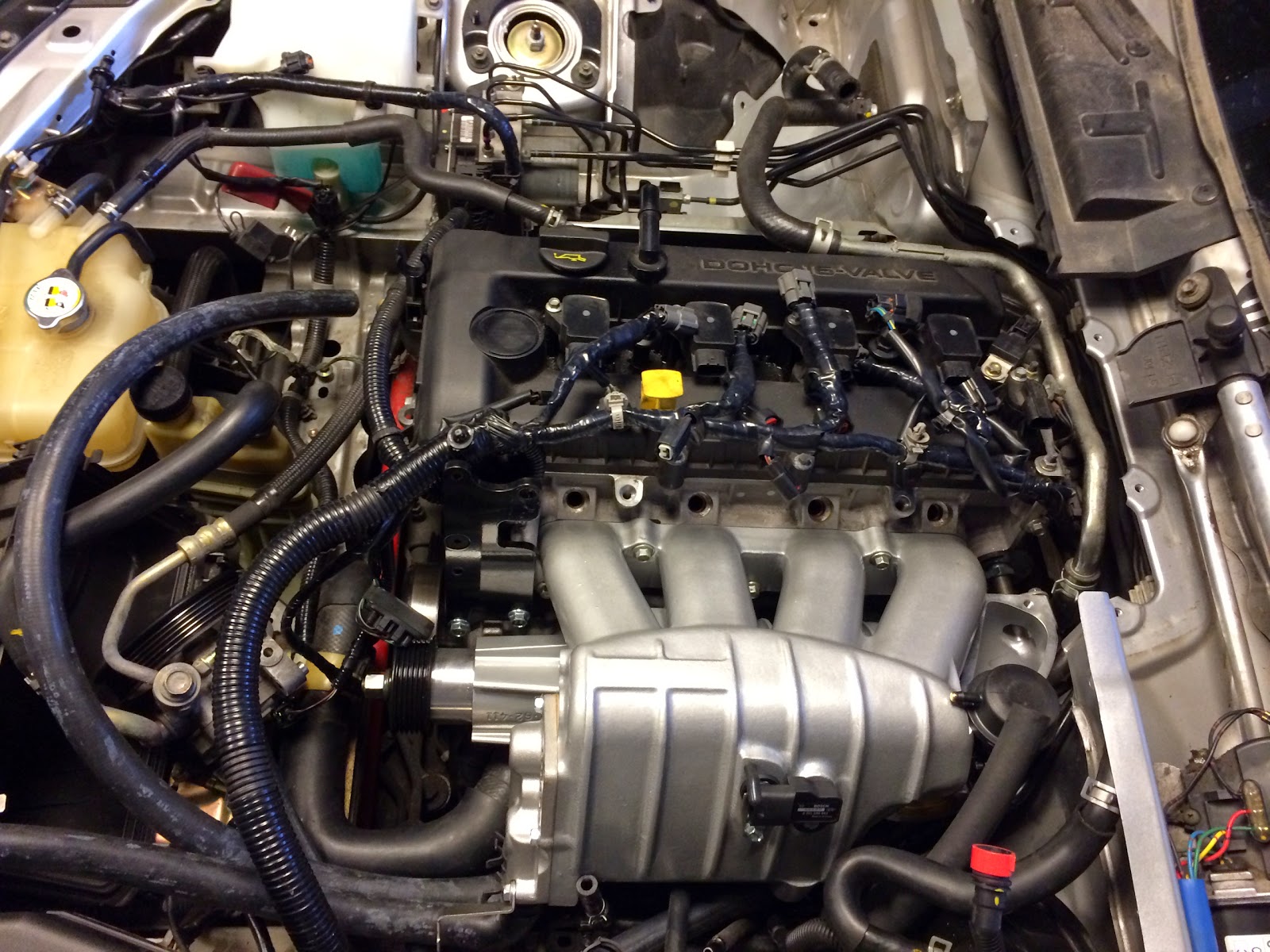 </div>
I have read several warnings about not using the supplied silicon gasket stuff that comes in a tube so I made my own from some fiber gasket material. Just use the upper manifold as a template.
<div class="separator" style="clear: both; text-align: center;">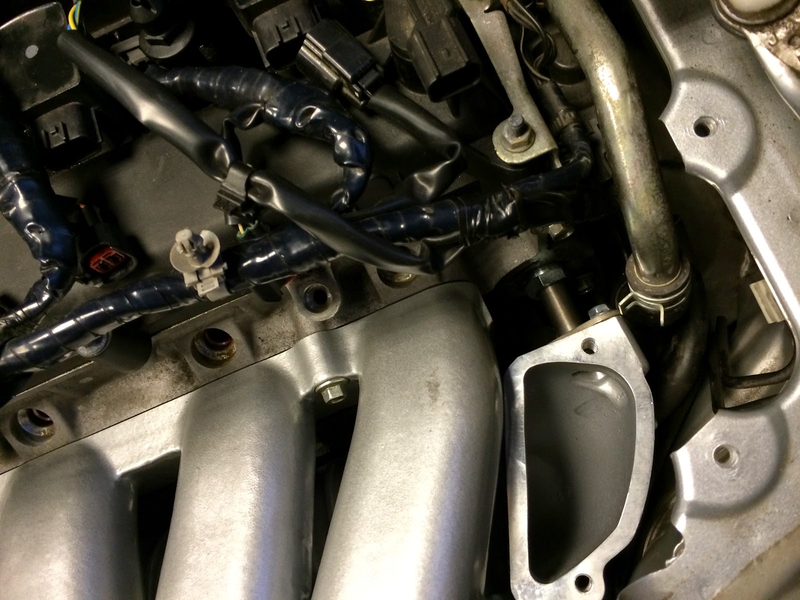 </div>
Upper manifold and fuelrail fitted. The new fuel rail has a pressure tester port which is nice. I’ll replace it with a permanent fuel pressure sensor later when the AEM infinity is sorted out.
<div class="separator" style="clear: both; text-align: center;"></div>
<div class="separator" style="clear: both; text-align: center;">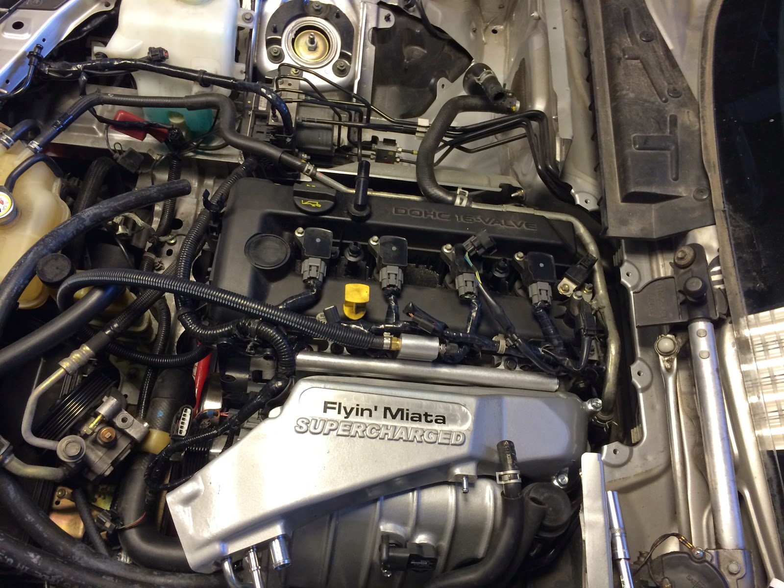 </div>
<div class="separator" style="clear: both; text-align: center;">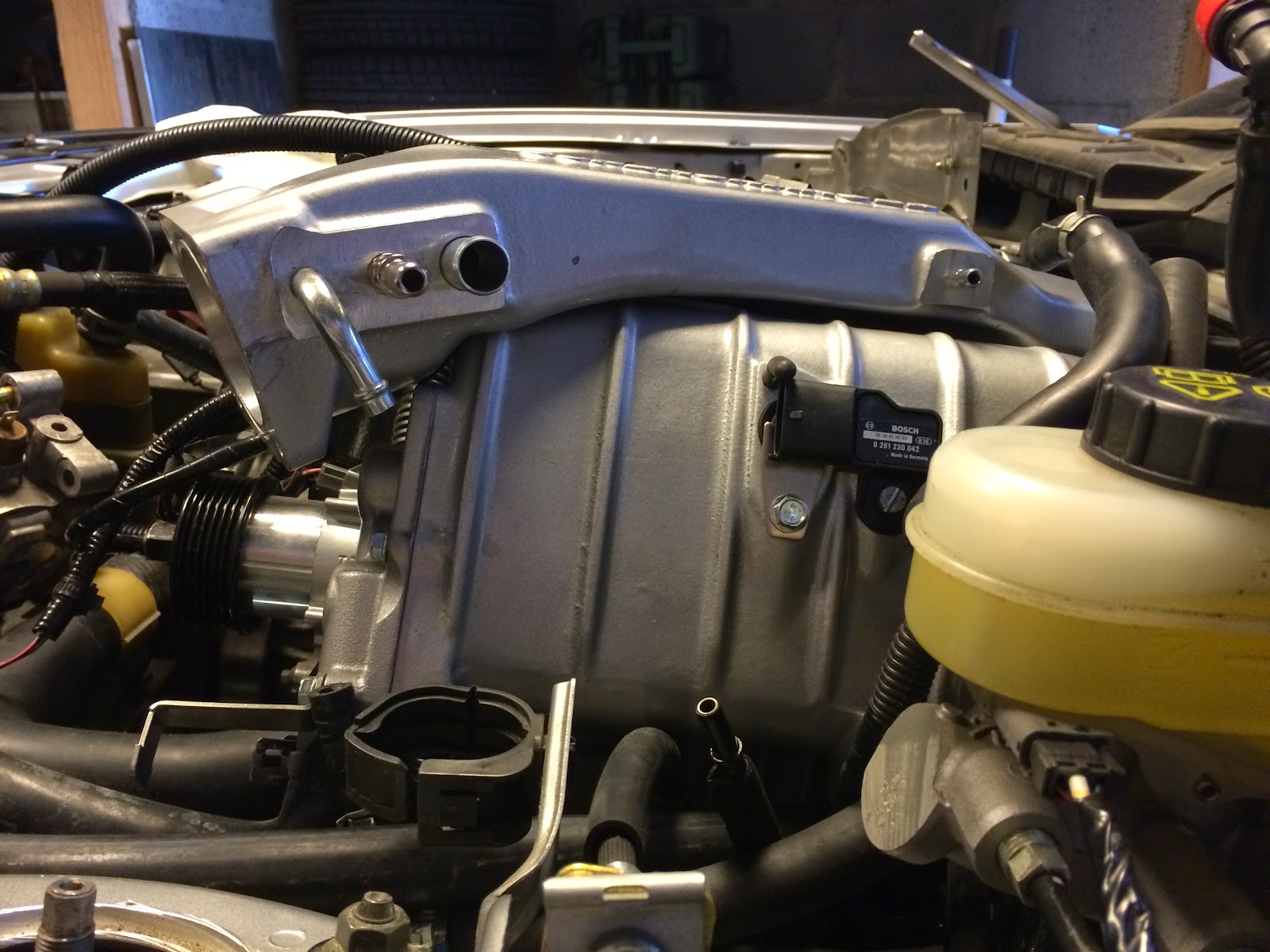 </div>
The electrical wiring is one of those things that should be done right the first time as it involves several critical sensors and components that could quickly destroy the engine if they stop working. I placed both the IC pump relay and fuse inside the fusebox instead of behind it like the instructions say.
<div class="separator" style="clear: both; text-align: center;">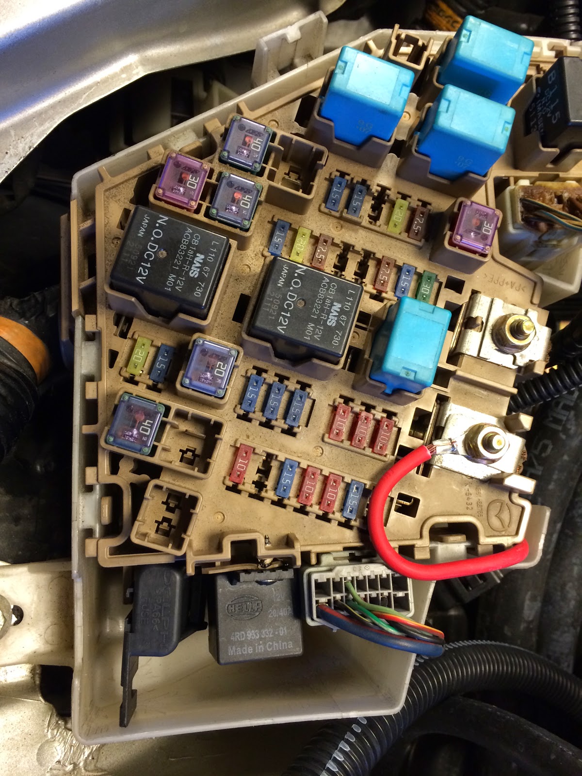 </div>
m.net says to solder the wires instead of using the crimps. I have learned that one should never solder any wires in an engine room where there is plenty of vibrations and temp variations. I have never had any problems using butt crimp connectors on any of my cars. Rule number one is to use a proper crimp tool. Not the crappy one with the 3 colors and wires trippers on the inside that barely dents the metal. Here is what I use:
<div class="separator" style="clear: both; text-align: center;">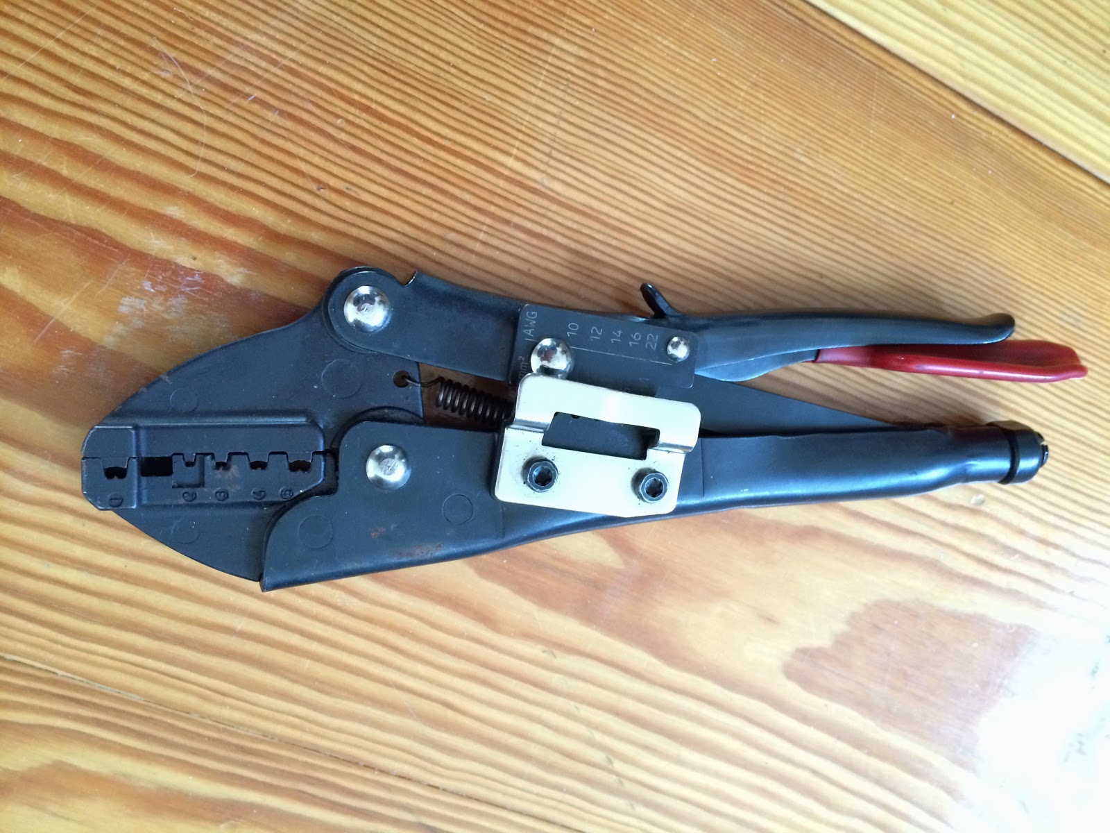 </div>
This crimps the butt connector by supporting it on the sides making the crimp super tight.
Rule number two is to use good quality heat shrink butt connectors (AND a heat gun…) as the ones supplied with the kit. They will protect and stiffen the crimp such that the crimped part will never move or twist. It will also somewhat prevent oxidation. I added an extra layer of black heat shrink on some of the more exposed crimps on top of the engine for added insurance and stealth.
<div class="separator" style="clear: both; text-align: center;">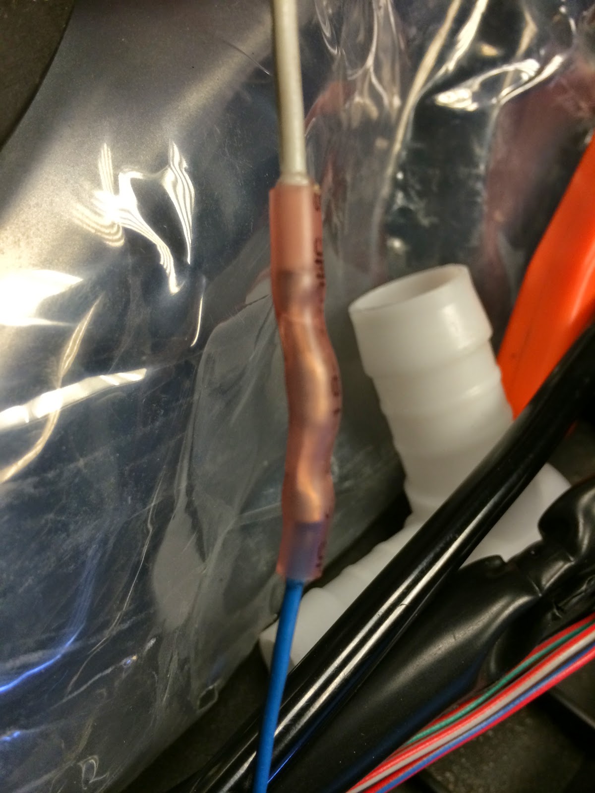 </div>
<div class="separator" style="clear: both; text-align: center;">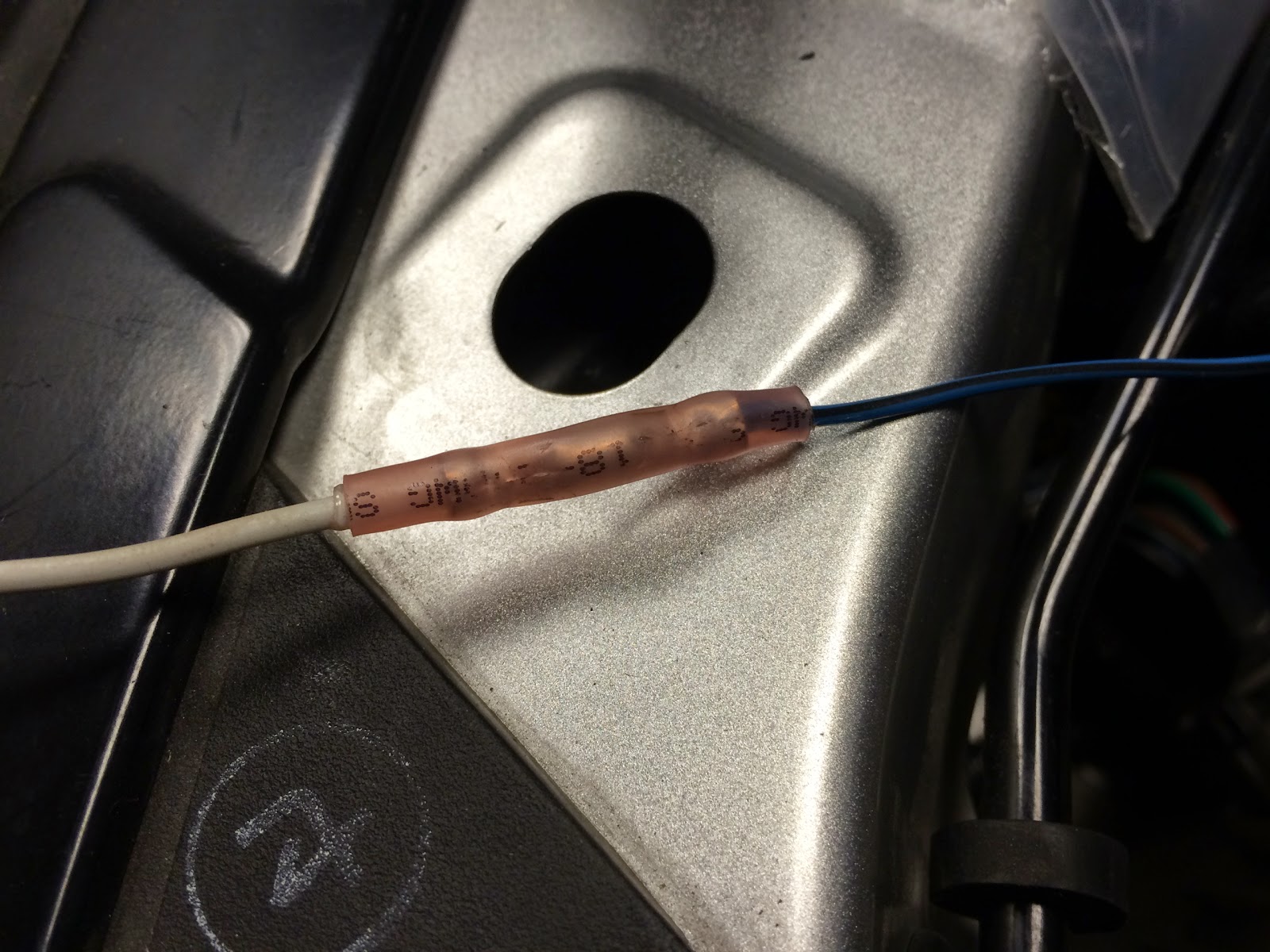 </div>
Since I’m boosting way more than 8 psi on this setup I use the Bosch 2.5 Bar TMap Map Sensor with IAT . Remember to order the pigtail as well as the stock one will not fit. Since it is a TMAP sensor it also incorporates a temp sensor for IAT that can be used instead of the GM sensor in the kit. I actually butchered the GM sensor and used it to plug the hole. The 2.5 sensor fits in the original position but has the wires facing forward. IMHO this actually looks cleaner and more OEM like.
<div class="separator" style="clear: both; text-align: center;">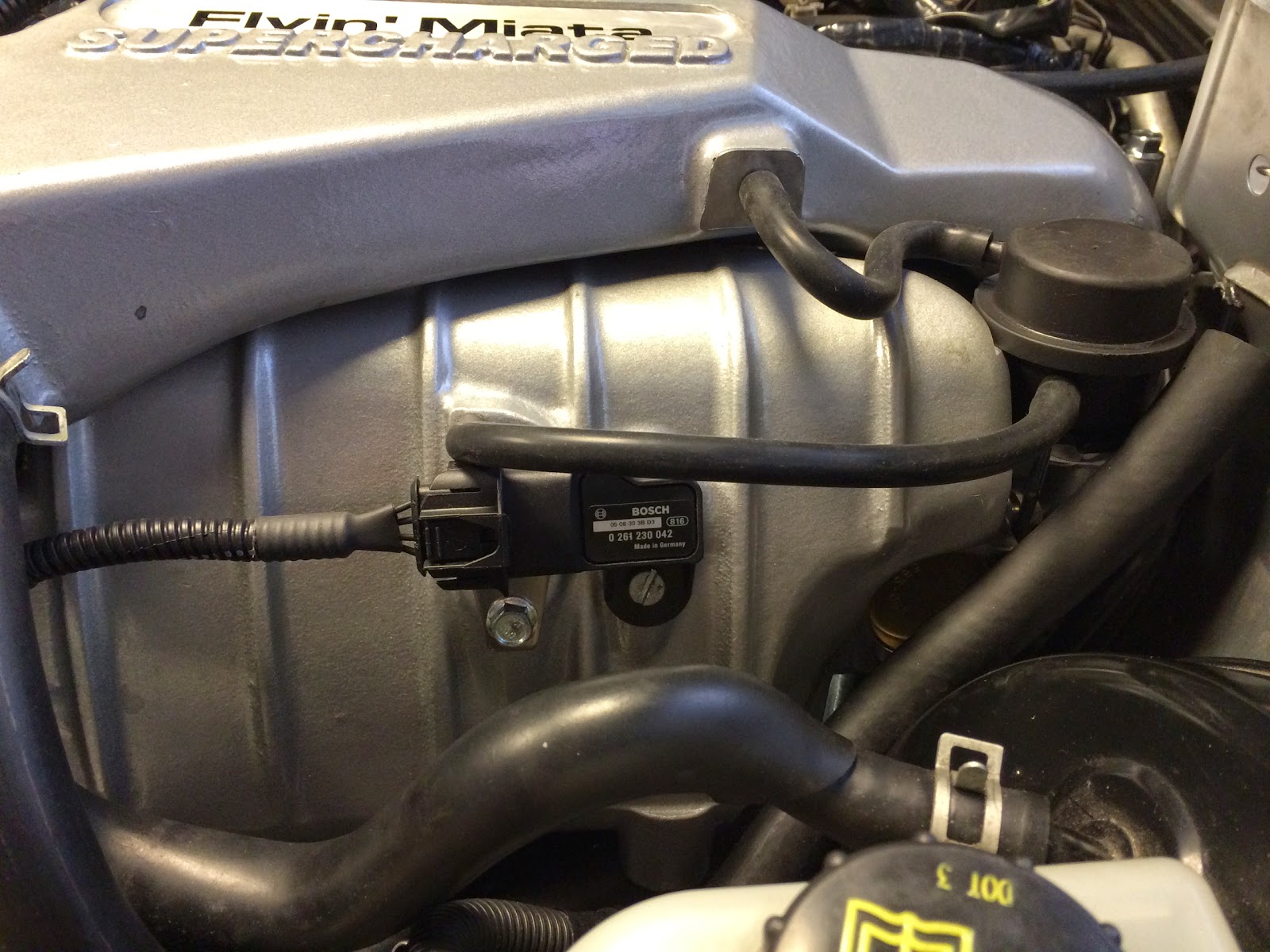 </div>
The MAP temp sensor doesn’t need calibration. I calibrated the MAP the hard way by datalogging output temp and voltage and comparing it to a digital manometer. I used a bicycle pump to generate the test pressure.
<div class="separator" style="clear: both; text-align: center;">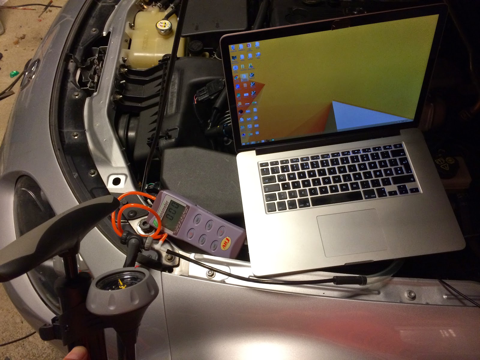 </div>
I used a non standard routing of the IC hoses as the coolant reservoir looks kind of misplaced when mounted by the shock tower. I was also able to reduce the number of 90 degree bends.
I have seen this done on the earlier installations. It requires some minor bending of steel by the headlight. Very stealth looking. The only sign of it is the black cap in front of the wiper fluid reservoir and the 90 bend going down to the heat exchanger.
<div class="separator" style="clear: both; text-align: center;">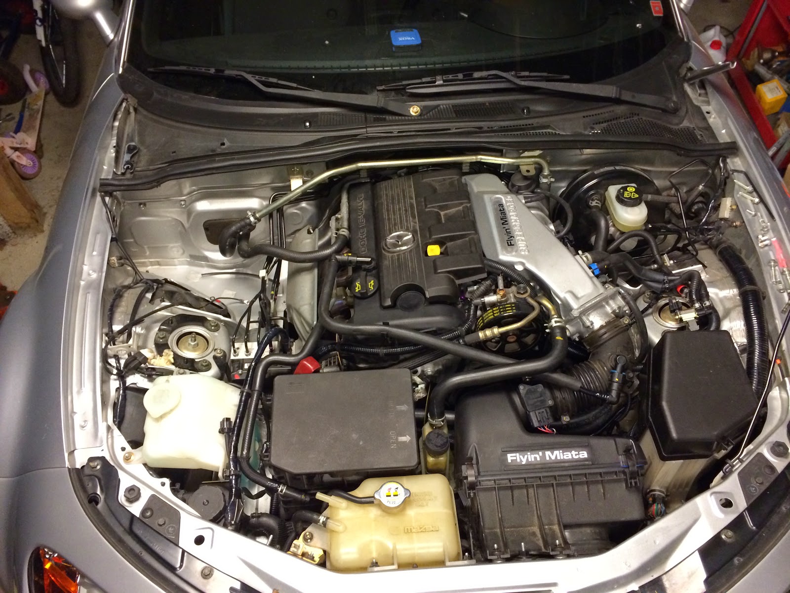 </div>
The most recent modification I did to the setup was to loop the coolant lines that goes in and out of the throttle body. They are there to prevent icing of the air trough the throttle body in cold conditions. I’m only using the car in the summer season so this is not needed on my car. Since both the TB and upper intake manifold is aluminum and there is no gasket isolating the two parts (o-ring) the upper manifold is heated by the TB and acts like a giant heater. This is not a problem with the OEM plastic piece as there is much less heat transfer.
Looping this line under the TB has an amazing effect on the surface temperature from not able to touch to near ambient temp. I have not measured the effect on IAT after blower but it must be good for something. For a track car this is a must IMHO. It is also easy to reverse if the car is to be used in the winter.
<div class="separator" style="clear: both; text-align: center;">
</div>
Comments